TBM Guidance & Surveying tools case study
Surveying experiences during the Austin Downtown Wastewater Tunnel Phase 1
Author: Darrell Bartley, Subterranean Solutions LLC.
Darrell has been working on numerous projects for many big construction companies as a tunnel surveyor during the last 25+ years. Currently he is offering tunnel surveying related services via his own company Subterranean Solutions LLC
Upon arrival to the job, the first step was to check the geometry on the plans and agree upon geometric configuration. Once that has been established, the coordinates and their parameters were entered into the TMS “Situation” and “Longitudinal” definitions to create the job axis. In this case the longitudinal was defined along flowline of the pipe. Next was to define profiles for the pipe and the bore diameters since this is a TBM project.
After the initial job control points were verified with GPS and tied together with a conventional traverse, we had to layout centerline stations at 100’ intervals on top of the ground for pre-construction pictures and videos. This was a breeze using the “string” mode in the TMS ProScan.
Once our first shaft was excavated to total depth and the bottom mud mat was poured, we filled the bottom of the shaft with gravel to an elevation 7 inches below the bottom of the TBM bore profile to allow for 6” of concrete and a 1” steel plate. We then laid out the cradle beams to launch the TBM using horizontal offsets in the Direval view in TMS ProScan and comparing them with the Deviation value using the TBM Bore profile. We then used the deviation values to layout the bore against the cylindrical shaft wall. This procedure would have been easier if we would have had the TMS SetOut programming on the instrument but unfortunately the functions in that portion of the software will not be used often enough to justify the extra cost for this project. A drill and shoot project would certainly be a different story.
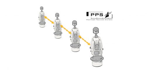
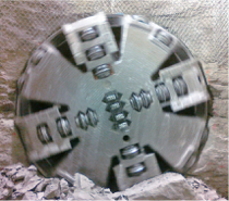
The TBM used on this project is a double shielded Lovat, 10.25’ Dia. with a gripper can. It has a Poltinger Precision Systems TBM Guidance System (PPS-TBM Guidance system). This system uses a Leica 1200 series theodolite which mounts to the tunnel wall and two (or more) fixed motorprisms mounted on the TBM. The theodolite uses a fixed back sight to check its orientation every 15 minutes and automatically turns and shoots the fixed prisms on the TBM to establish their global coordinate position. From there it calculates the local coordinate values for the fixed prisms and projects the TBM head position and references that to the design axis to convey the position and attitudes to the operator via a computer monitor. This system needs to be pre-loaded with a centerline axis file which has to be defined with coordinates and elevations at one meter intervals. This task is simplified by the “calculations” option in the TMS software. This job consists of 18,600 linear feet and the calculations required for the centerline file took less than one second.
During the initial set up of the TBM in the first shaft, the motorprisms had to be relocated several times. I did not think this was a problem to resurvey them each time until I realized that as the TBM was advancing in the starter tunnel, it had crushed the right guide rail which in turn resulted in the wrong vertical and horizontal offsets for the prisms. After we had mined in far enough to expose 100’ of tunnel wall, I used a 4’ level and held it on the side of the tunnel (vertically) sliding it up and down until it was level and made a mark midway on the level, on the tunnel wall (essentially marking the asbuilt springline of the excavation). I then shot and stored those points so I could later import them into the TMS software for their horizontal and vertical offsets compared to the design axis.
I then exported the database from the guidance system at one foot intervals to retrieve the recorded position of the TBM at each one foot location. By direct comparison of the values from the TMS data and the PPS data, I was able to correctly adjust the horizontal and vertical offsets of the motorprisms within the PPS-TBM system. We then mined another 100’ and I repeated the above process to verify the changes. I can’t think of an easier, quicker and more accurate way that could have been done. I repeated this process once again after 1000’ with no adjustments necessary.
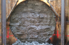
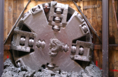
Using Amberg TMS in conjunction with the Poltinger Precision Systems Guidance system has proven to be the key factors in the Bull’s eye hole through at the Comal shaft of the Austin Downtown Wastewater Tunnel.

After pushing the TBM through the Comal shaft and starting the second reach, we started setting 90” Hobas pipe in the first reach.To set the pipe we use a Topcon TP-L4BG laser in conjunction with a locamotive and pipe carrier. In order to clear the pipe carrier with the laser for the crew to set the pipe properly on grade, the laser is set along the springline of the pipe. As stated earlier, our design axis longitudinal defenition was created along the plan Flow line of the pipe.
To set the laser at the proper elevation for the crew to use, our surveyors position the gun off of the tunnel control established during mining operations and shoot the laser location looking for a vertical offset in the string mode of the ProScan of a +3.75’ (Half the pipe diameter). Once the laser is positioned at springline, the surveyor uses the remote control for the laser to dial the laser down the tunnel wall a couple hundred feet and shoot reflectorless where the laser is hitting on the wall to verify the same vertical offset of +3.75’, ensuring the proper slope is carried throughout the reach. The pipe crew uses a torpedo level on the side of the pipe to locate the springline of the pipe then uses the laser remote to dial the laser over to where he is holding the level and raises or lowers the pipe until the laser passes through the center of the torpedo level, thus setting the pipe on the proper grade. The pipe is then blocked in place and pipe carrier is removed from the pipe and grade on the pipe is checked again before traveling out of the tunnel for the next pipe.
The next scenario made easy with the use of Amberg TMS is a connection we needed to make to an existing 96” concrete tunnel with a 90” Hobas (Fiberglass pipe) at a 56 degree angle of incident. The azimuth of the Hobas pipe (with the flow) was 69 degrees and the azimuth of the exiting pipe and flow was 103 degrees. The hobas pipe needed to be cut on top of the ground before lowering into the tunnel. Since both flows needed to match at springline, on the pipe to be cut, I once again took a torpedo level and used it vertically to mark springline where I wanted to start the cut (1) and another springline mark at the other end of the pipe (2). Since the pipe was not level, I set up the Leica 1201+ and stored the springline marks as points 1 and 2 respectively using reflectorless technology.
I had already taken shots on the existing concrete pipe and determined the radius as 5.05’. I then took out my laptop and using point #1 and the asbuilt azimuth to point #2 (as the pipe was resting) I then calculated my situation, turning 34 Degrees (Complimentary angle) from #1 to #2 to the right then added 90 degrees to essentially create a perpendicular line to the existing flow in the concrete pipe. Projected a horizontal distance of 5.05’ to establish the virtual centerline of the concrete pipe. I then added 90 degrees to establish coordinates along the virtual pipe centerline 100’in both directions. Then using points #1 and #2, I projected the slope to define the elevation (longitudinal) of the initial virtual centerline and defined the longitudinal portion of the program as level slope. Then I defined a theoretical profile using my defined (centerline-springline axis) and the pipe radius of 5.05’. I quickly exported the job info to my CF card, put it back into the total station and shot (reflectorless) on the inside of the pipe to be cut and marked every couple of inches a point indicated as zero deviation in the string measurement mode of TMS ProScan. I could not have been any more pleased with the ease and acuracy of the layout and I am confident that when we do set the cut pipe in place it will marry up to the existing pipe perfectly.
When the cut pipe was lowered into place, the only spots not flush together were due to the minor imperfections of the existing concrete from when we excavated to expose it.
One cut, perfect fit!